This article details the electronics I put together for my DIY CNC machine.
Computer
This is a very nice sized little self contained computer that is plenty powerful enough to run Mach 3, particularly with a SmoothStepper interface card. I'm inheriting it from my wife, whom I've upgraded to a more powerful Dell computer.
Enclosure
Rittal 19" x 19" x 12" NEMA Style Box
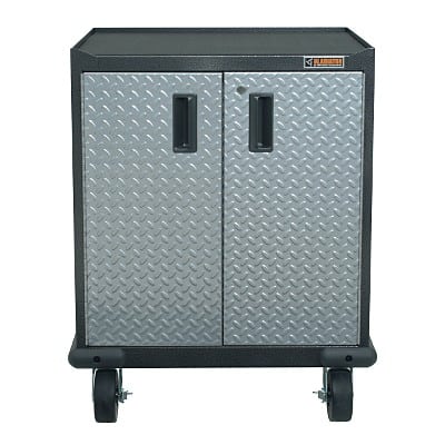
I got a couple of these really nice NEMA boxes off eBay for a great price. I will mount the NEMA enclosure on the side of a rolling cabinet I got from Sears:
In addition to the NEMA attached to the side, I will also mount a swing arm to hold a touchscreen monitor, keyboard, and mouse. I may also set up the swing arm to take a pendant or control panel. Lastly, there will likely be a USB hub available.
Inside the NEMA box will be the following components:
- 6 x Driver Sub-Chassis: A driver sub-chassis mounts all of the components associated with a Geckodrive for stepper or servo.
- DC Power Supply for steppers and servos
- Breakout Board: Smoothstepper as I want all 6 channels available and probably some other signals as well
- VFD interface: PWM or other interface for spindle speed. The VFD itself will be mounted externally to the NEMA enclosure.
- Relay Board: To control coolant, spindle on/off, and spindle direction.
- E-Stop circuitry (Time delay?)
External connections to the NEMA enclosure:
- 110V AC
- E-Stop button (plus E-Stop daisy chain?)
- Master On/Off?
- Pilot Light?
- USB Input from the PC to the Smooth Stepper breakout board
- 6 Channels of Motor Drive with Encoder connections for any of the channels that are servos.
- VFD and Spindle Connections
- Coolant On/Off Connections
Here is a general overview of the enclosure layout showing the major components:
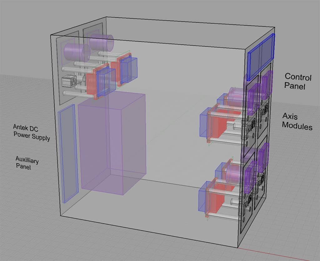
The four main axis modules are on the front panel mounted via cutouts. These 4 are for the X, Y, Z, and A axes. The extra 2 axis modules are on the rear, with the power supply right below them.
The control panel at top provides E-Stop, master power and similar functions. The auxilliary panel provides connections for the USB from PC, VFD, Limit Switches, coolant, and other such functions.
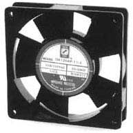
I have ordered a small fan from Willy Electronics that runs on 120V AC to install in the top of the enclosure so I can draw any warm air out and keep things cool.
The individual circuit boards and the big DC power supply are mounted on a sub-plate that goes into the enclosure:
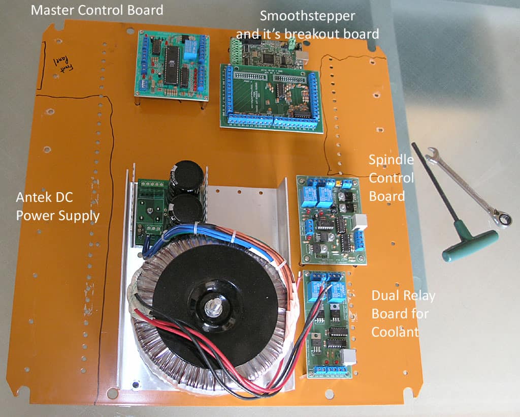
I've labeled the boards so you can see what's what. The black outlines are Sharpie to indicate where the axis modules protrude so I am careful to leave clearance. The PC
boards are mounted on standoffs available at Radio Shack.
This is a good idea for a whole lot of reasons, not the least of which is that you can wire it up all nice with the sub-plate sitting on a table and then install the whole works in one shot.
Cutting Most of the Cutouts in the NEMA Enclosure
I will still need holes for the cooling fan, but I want to make sure I understand the clearances and location of everything else before I try to position the fan. My current thinking is to put it in the door next to the hinge and up high to exhaust the warm air. Wish I had a louver punch!
Here are some piccys:
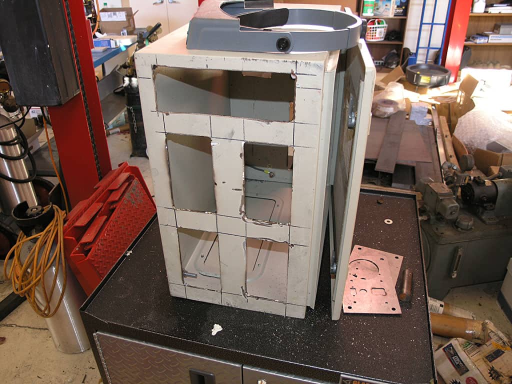
The panel inserts cover the holes. 4 axes on front, with a master control panel at the top. I could possibly also exhaust the fan at the right side of that control panel...
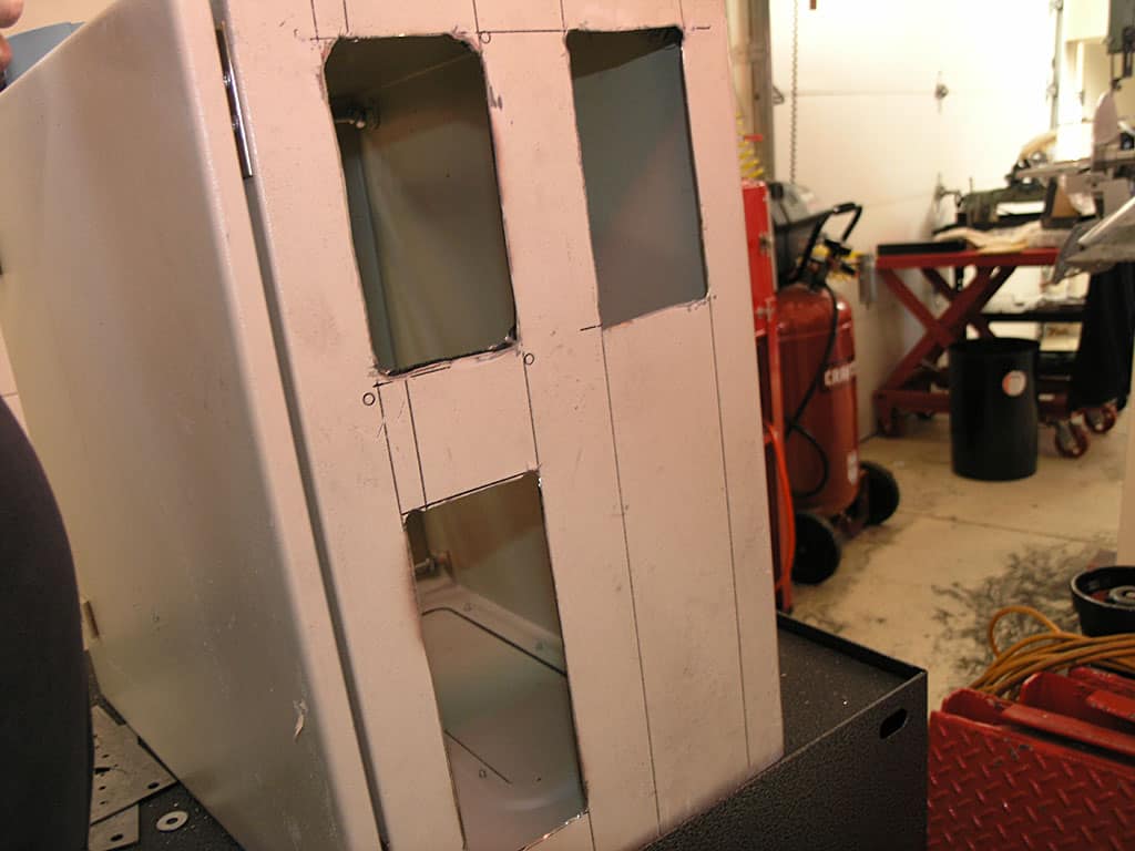
Three rear panel cutouts. Top 2 are for 2 more axes. Bottom will be for all the auxilliary connectors for limits, coolant relay control, and VFD control...
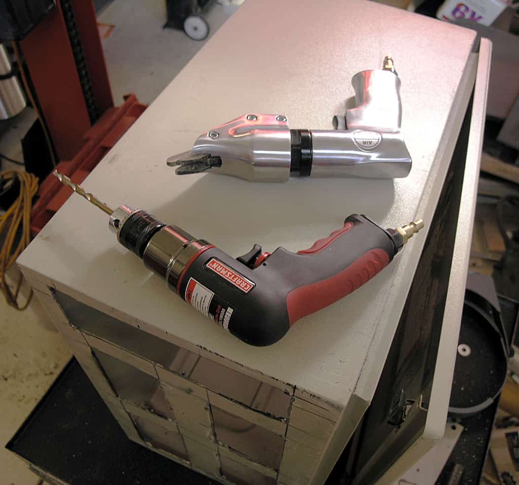
The cutouts were made by drilling a hole in each corner and then connecting the dots with an air nibbler...
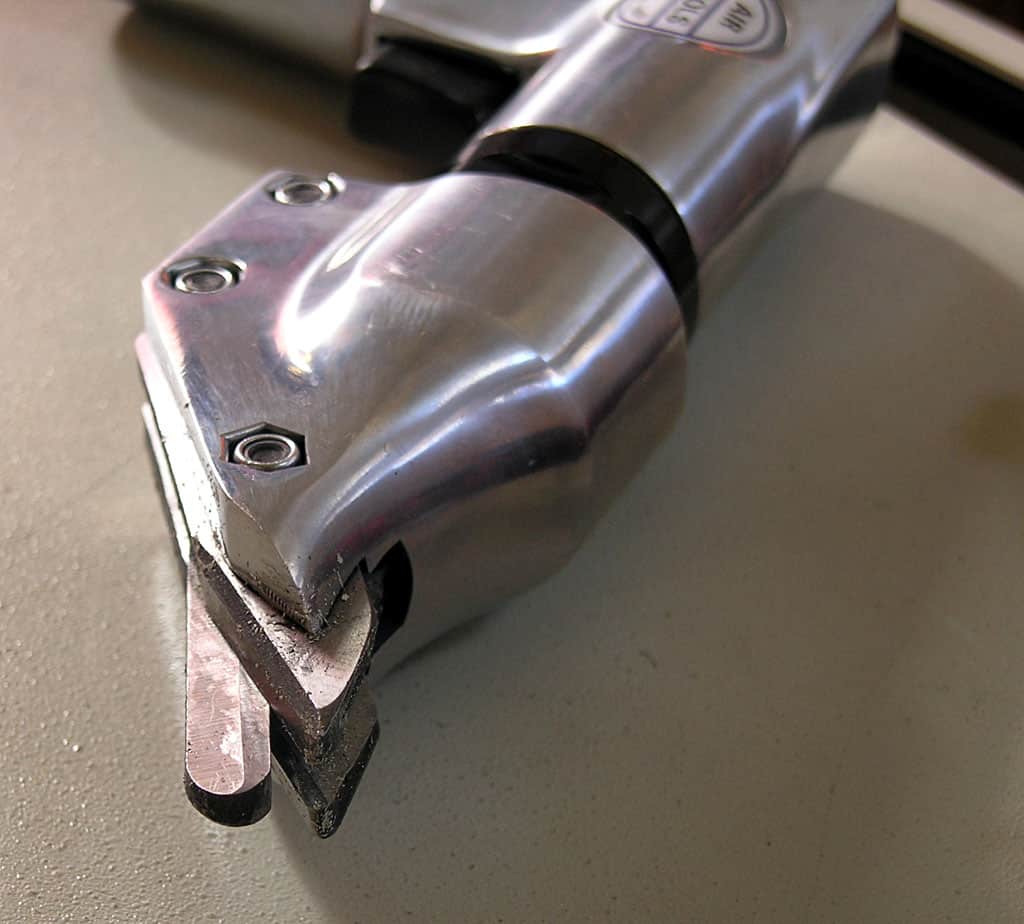
The air nibbler has hardened jaws and went through the thick gauge steel box like butter...
DC Power Supply
I ordered a PS-10N70 power supply from Antek to power the servos on my mill. Here is a photo:
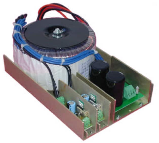
It was $150 + $10 shipping, which seems very reasonable. This is a 70V supply, which leaves a little margin for the 80V limit on the Geckodrives. Antek is run by a fellow named John Ango. I've ordered toroidal transformers from him before and he's a good guy to do business with. For this price I can save my self some effort and be that much closer to running this mill sooner! This particular supply is 1000 watts but he also has 1500 watt supplies if you want more beef.
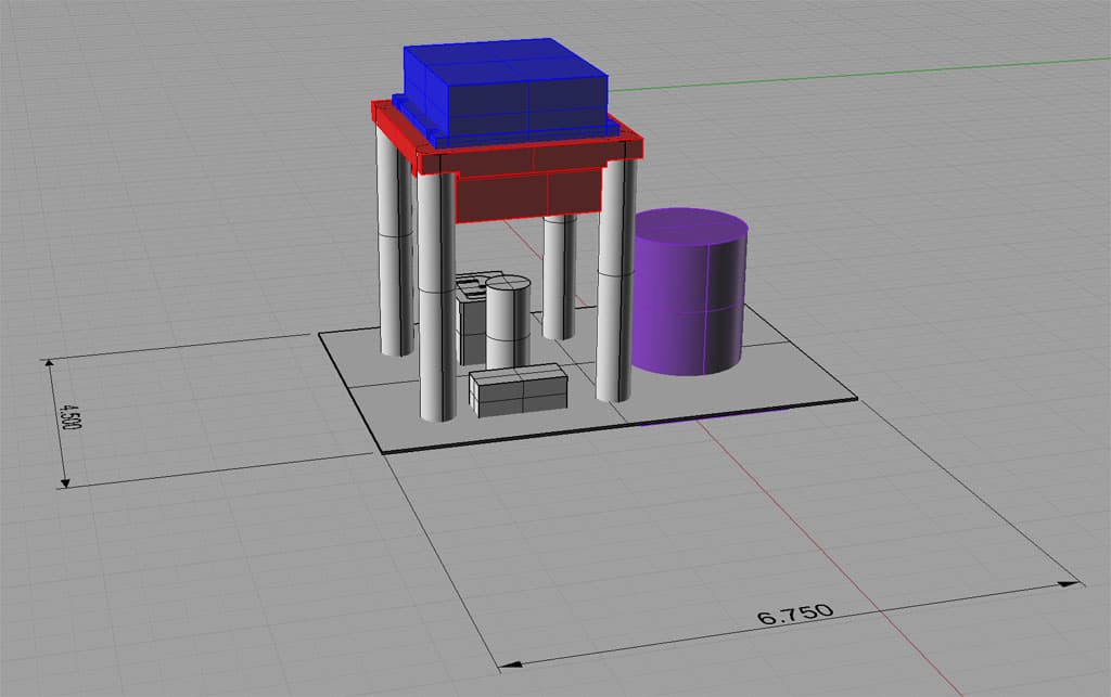
Axis Modules
The idea here is to mount all the components associated with a single axis. Check the Axis Module page for details, but here is a 3D model of an axis module:
Check out the CNC4PC and Smoothstepper Electronics
Be the first to know about updates at CNC Cookbook
Join our newsletter to get updates on what's next at CNC Cookbook.